
What is a Current Transformer (CT)?
Current transformers (CTs) are essential for monitoring and measuring electrical current in high-voltage or high-current systems safely and accurately. By reducing large currents to a manageable level, CTs allow for effective connection to metering devices and protective relays without direct exposure to the full circuit load.
The principal of operation of a basic current transformer is slightly different from that of an ordinary voltage transformer.
Unlike the voltage or power transformer, CTs consists of only one or very few turns on its primary winding. This primary winding can be of either a single flat turn, a coil of heavy duty wire wrapped around the core or just a conductor or bus bar placed through a central hole.
Due to this type of arrangement, the current transformer is often referred too as a “series transformer” as the primary winding, which never has more than a very few turns, is in series with the current carrying conductor supplying a load.
The secondary winding however, may have a large number of coil turns wound on a laminated core of low-loss magnetic material.
This core has a large cross-sectional area so that the magnetic flux density created is low using much smaller cross-sectional area wire, depending upon how much the current must be stepped down as it tries to output a constant current, independent of the connected load.
The secondary winding will supply a current into either a short circuit, in the form of an ammeter, or into a resistive load until the voltage induced in the secondary is big enough to saturate the core or cause failure from excessive voltage breakdown.
Unlike a voltage transformer, the primary current of a CT is not dependent of the secondary load current but instead is controlled by an external load. The secondary current is usually rated at a standard 1 Ampere or 5 Amperes for larger primary current ratings.
Current transformers can reduce or “step-down” current levels from thousands of amperes down to a standard output of a known ratio to either 5 Amps or 1 Amp for normal operation. Thus, small and accurate instruments and control devices can be used with CT’s because they are insulated away from any high-voltage power lines.
Most current transformers have a standard secondary rating of 5 or 1 amps with the primary and secondary currents being expressed as a ratio such as 100/5. This means that the primary current is 20 times greater than the secondary current so when 100 amps is flowing in the primary conductor it will result in 5 amps flowing in the secondary winding. A CT with a turns ratio of 500/5, will produce 5 amps in the secondary for 500 amps in the primary conductor, 100 times greater. However, if the primary conductor has 1000 Amps going through it, an ideal transformer with a turns ratio of 500/5 would give 1000*5/500 = 10A in the secondary circuit.
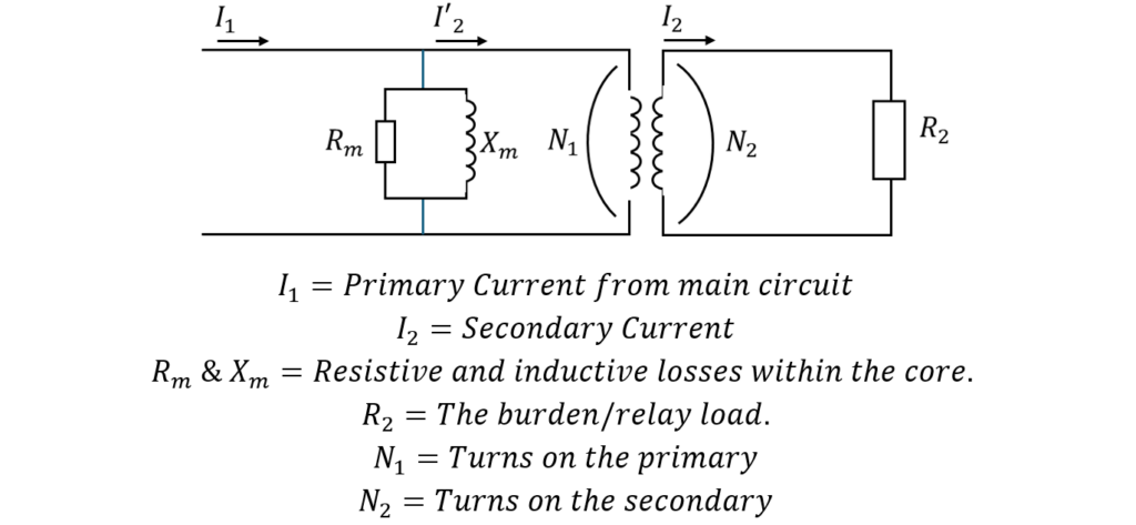
A CT can be drawn as an equivalent circuit shown below:
Knee point voltage
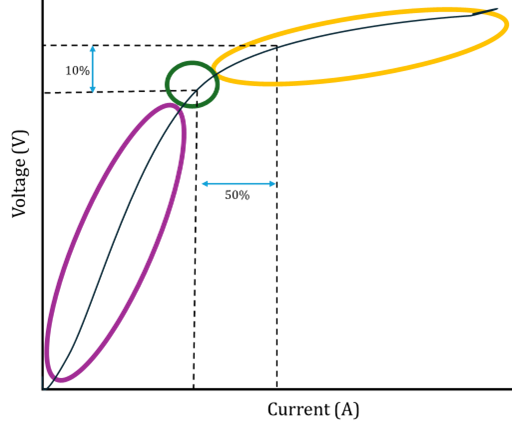
1. Normal Operation: Core Magnetisation is Linear
When a CT operates within its intended range, the iron core behaves in a largely linear region of its magnetisation (B‑H) curve:
- The secondary burden draws current proportional to the primary current.
- Only a small amount of current (called magnetising current) is required to energise the core.
- The induced secondary voltage is just enough to drive the required secondary current through the connected burden.
At this stage, the CT core is not close to saturation, and the relationship between voltage and magnetising current is stable.
2. Reaching the Knee‑Point Voltage
The knee‑point voltage is defined (per IEC/BS standards) as the point on the excitation curve where:
An increase of 10% in secondary voltage results in an increase of 50% or more in magnetising current.
This point is visually where the excitation curve bends sharply, hence the term knee point.
Why this happens:
- The core is almost saturated.
- Any small increase in voltage forces the CT to try to create more flux, but the core cannot accept it efficiently.
- The magnetising current rapidly increases to compensate.
Physically, the CT has reached the practical limit of what its core material can magnetically support.
3. After Knee Point: Core Saturation and Distortion
Once past the knee point:
- The CT becomes highly saturated.
- The majority of current drawn is magnetising current, not useful secondary current.
- The CT can no longer accurately transform the primary current.
- Secondary current becomes distorted and clipped.
This is why protection CTs must be specified with a knee‑point voltage high enough to avoid saturation during fault conditions. In other words, you should pick a CT whose knee point is high enough that it still behaves properly at fault current.
To be safe, the knee point needs to be at least double the voltage the CT has to produce during the worst fault.
Why is a CT not to be left open circuited?
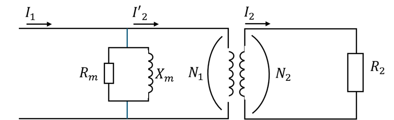
Imagine the CT’s equivalent circuit. Under normal conditions, the primary current is transformed into a smaller secondary current
. Most of this current flows out through the secondary winding to the burden (like protection relays), and only a small amount becomes magnetising current in the core (the current through Rm and Xm).
If the secondary is left open‑circuited, there is no path for to flow. Because the circuit isn’t complete, the CT can’t send current to the burden. Instead, almost all of the primary current ends up going into magnetising the core.
When this happens, the core tries to create a much larger magnetic flux. To do this, the CT generates a very high voltage on the open secondary terminals. This voltage can be extremely dangerous, high enough to damage insulation, cause arcing, and in extreme cases seriously damage the CT.
How is a CT described?
Lets use 10 VA Class 5P 15 as an Example
A current transformer’s rating tells you three main things:
- Its rated burden (in VA)
- Its accuracy class
- Its accuracy limit factor (ALF)
1. Burden Rating – 10 VA
This tells you how much load (burden) the CT can supply at rated secondary current without exceeding its accuracy limits.
- If the CT is a 5 A secondary CT, and the burden is 10 VA,
then:
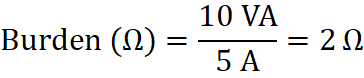
This means, the CT can deliver 5 A to a burden of 10 VA (or 2 Ω).
2. Accuracy Class – 5P
The class tells you what type of accuracy the CT provides and for what purpose.
5P means:
- 5% maximum ratio error at the rated accuracy limit factor
- P = Protection class CT
So a Class 5P CT is a protection‑grade CT, not a metering CT. It can have up to 5% error when operating at its ALF.
3. Accuracy Limit Factor – 15
This is the multiplier of rated current up to which the CT will still meet its accuracy.
ALF = 15
Means the CT must remain within 5% error up to:
So:
✔ At 75 A secondary (equivalent to 15 times rated current),
✔ The CT will still have no more than 5% error.
This is important during fault conditions, where currents rise sharply.
In other words, A 5A CT described as 10 VA Class 5P 15 means:
- It can supply 5 A into a 10 VA burden
- Up to 15 × rated current (75 A secondary)
- With a maximum error of 5% at that level
- It is a protection (P‑class) CT
Or:
10 VA Class 5P 15” means the CT can supply 5 A into a 10 VA burden, and it will stay within 5% accuracy up to 15 times rated current. The ‘P’ shows it is a protection‑grade CT.”